ASC Field Illumination
(→acquisition) |
|||
| (3 intermediate revisions by one user not shown) | |||
| Line 8: | Line 8: | ||
* mirror slide | * mirror slide | ||
** alternatively: reflective surface (i.e. glass slide, gold-coated surface) | ** alternatively: reflective surface (i.e. glass slide, gold-coated surface) | ||
| − | ** for | + | ** to check for field illumination with immersion objectives, one should consider the use of the Leica Z-resolution mirror |
| + | |||
== acquisition == | == acquisition == | ||
* set the laser of interest for illumination | * set the laser of interest for illumination | ||
| Line 25: | Line 26: | ||
== images == | == images == | ||
| − | <gallery | + | <gallery> |
file:Field illumination zeiss mirror.jpg|Zeiss mirror slide | file:Field illumination zeiss mirror.jpg|Zeiss mirror slide | ||
| + | file:Z-resolution leica mirror.jpg|Leica Z-resolution mirror slide | ||
file:Field illumination japanese flag.jpg|"Japanese flag", reflected light image of mirror slide, Zeiss LSM 510, 10x/0.45, zoom 0.7, 594 nm laser, "HiLo" LUT | file:Field illumination japanese flag.jpg|"Japanese flag", reflected light image of mirror slide, Zeiss LSM 510, 10x/0.45, zoom 0.7, 594 nm laser, "HiLo" LUT | ||
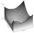
file:Field illumination surface plot.jpg|Surface plot of illumination pattern | file:Field illumination surface plot.jpg|Surface plot of illumination pattern | ||
| Line 32: | Line 34: | ||
file:Plot of 10xillumination594hft-405-488-594CH1.jpg|Line Profile of illumination pattern, diagonally across center | file:Plot of 10xillumination594hft-405-488-594CH1.jpg|Line Profile of illumination pattern, diagonally across center | ||
</gallery> | </gallery> | ||
| + | [[category:ASC]] | ||
__NOTOC__ | __NOTOC__ | ||
Latest revision as of 09:50, 1 October 2009
The two images acquired via Fluorescence and Brightfield Imaging already gave an impression of the field illumination. Homogeneous illumination is particularly important for quantitative analysis, i.e. the comparison of intensities in different regions of the field of view. Therefore the following test provides a more quantitative analysis of the field illumination. Reasons for the illumination not being in the center might be:
- lasers not coupled well into the fiber
- fiber not coupled well into the scan-head
- objective misaligned/damaged
- pinhole not centered
Due to that, it makes sense to not only test 10x objective + 488 nm laser, but also other combinations. Try to compare images with open vs. closed pinhole to check for the pinhole alignment.
[edit] requirements
- mirror slide
- alternatively: reflective surface (i.e. glass slide, gold-coated surface)
- to check for field illumination with immersion objectives, one should consider the use of the Leica Z-resolution mirror
[edit] acquisition
- set the laser of interest for illumination
- set pinhole to 1 AU
- set up beam path for reflection (i.e. 80/20 splitter, AOBS in reflection mode; detection of illumination wavelength)
- focus on reflective side of the mirror
- try to obtain "japanese flag"-like image (use i.e. "Range Indicator" LUT)
- for quantitative measurements, do not oversaturate the center
[edit] analysis
- Is the illumination centered well?
- How big are the differences in intensity between center and edges?
- ways of visualization in Fiji:
- Surface Plot: Analyze > Surface Plot...
- Line Profile: draw a line across the center of the image, then Analyze > Plot Profile
[edit] images
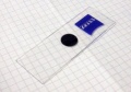
Zeiss mirror slide
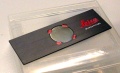
Leica Z-resolution mirror slide
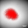
"Japanese flag", reflected light image of mirror slide, Zeiss LSM 510, 10x/0.45, zoom 0.7, 594 nm laser, "HiLo" LUT
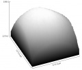
Surface plot of illumination pattern
Surface plot of illumination pattern, inverted
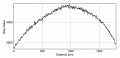
Line Profile of illumination pattern, diagonally across center


