Biopolis Dresden Imaging Platform

Basic Optical Concepts

Refraction

Theory

Refraction is the blessing and the curse of microscopy.

Light travels at different speeds in different materials. It is fastest in vacuum with 299,792,458 meters per second. Slowing down when entering an optically more dense material, light gets deviated from its direction of travel. This is called refraction. The ratio n between the speed of light in vacuum (c) and that in the respective material (v) (n=c/v) is called refractive index. The refractive index is a bulk physical constant of that material. It is dependent on the temperature of the material and the energy (frequency) of the light waves traveling through.

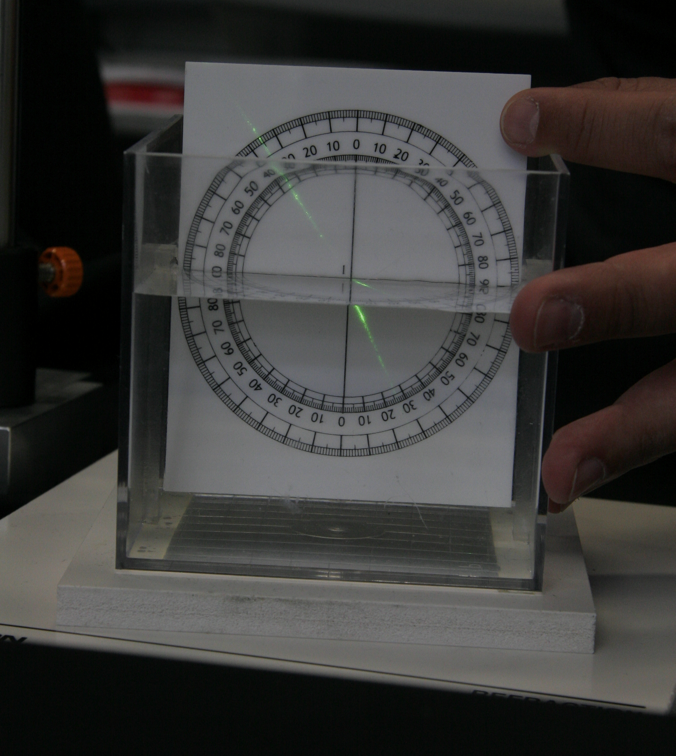
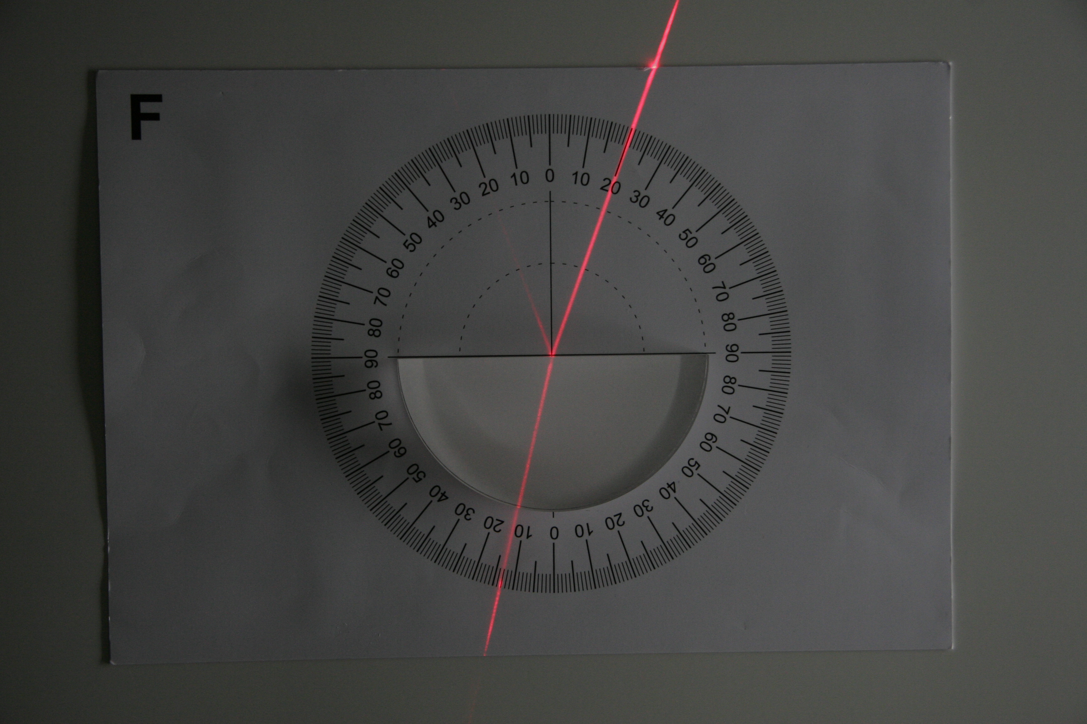
Snell's law describes the relationship between refractive indices of two adjacent isotropic materials and angles of incidence of light traveling through the boundary between the two:

sin(a1) / sin(a2) = n2 / n1


Hands-on

Refraction I - Laser into Waterbath

Concept demonstrated

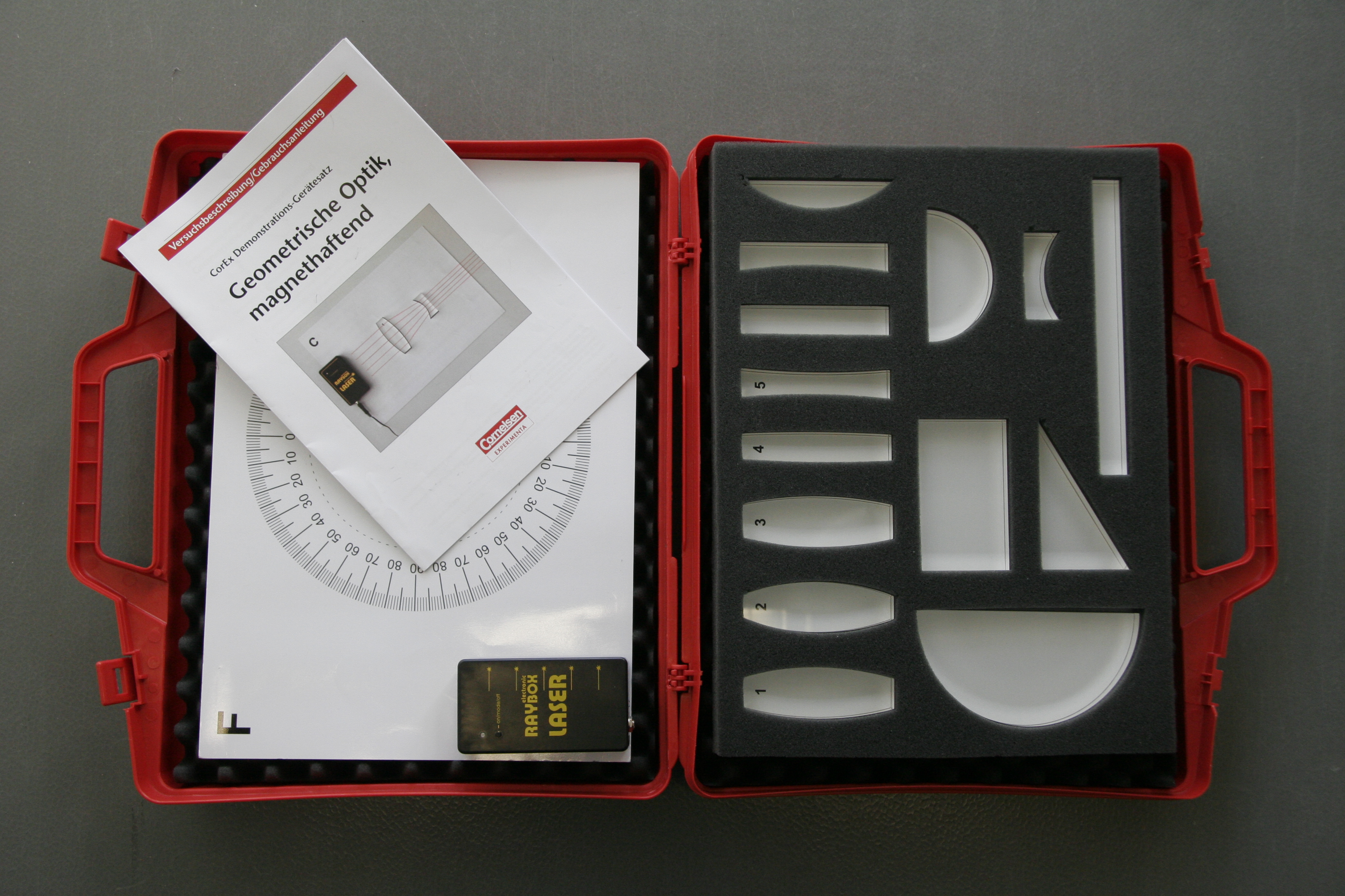
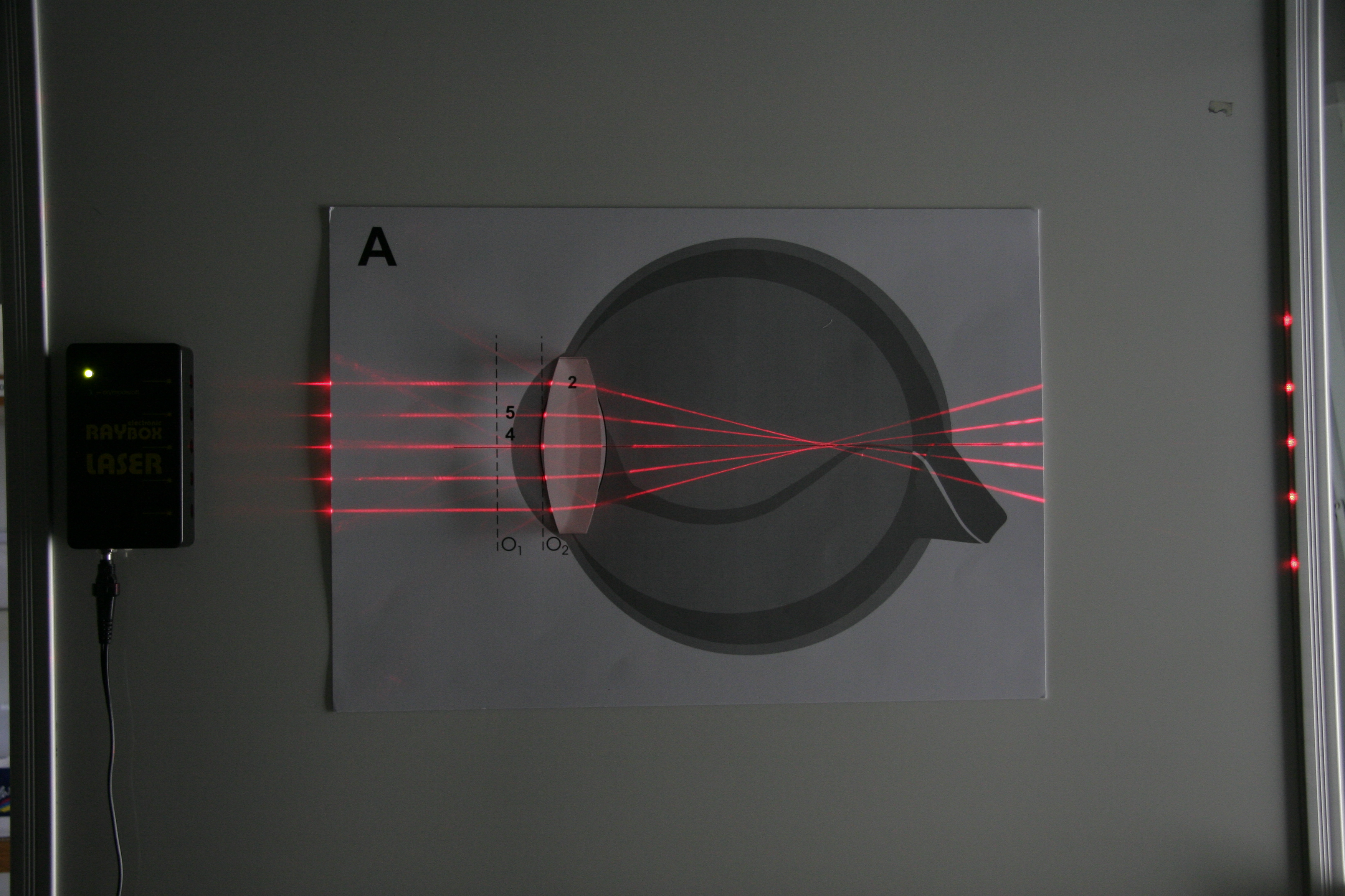
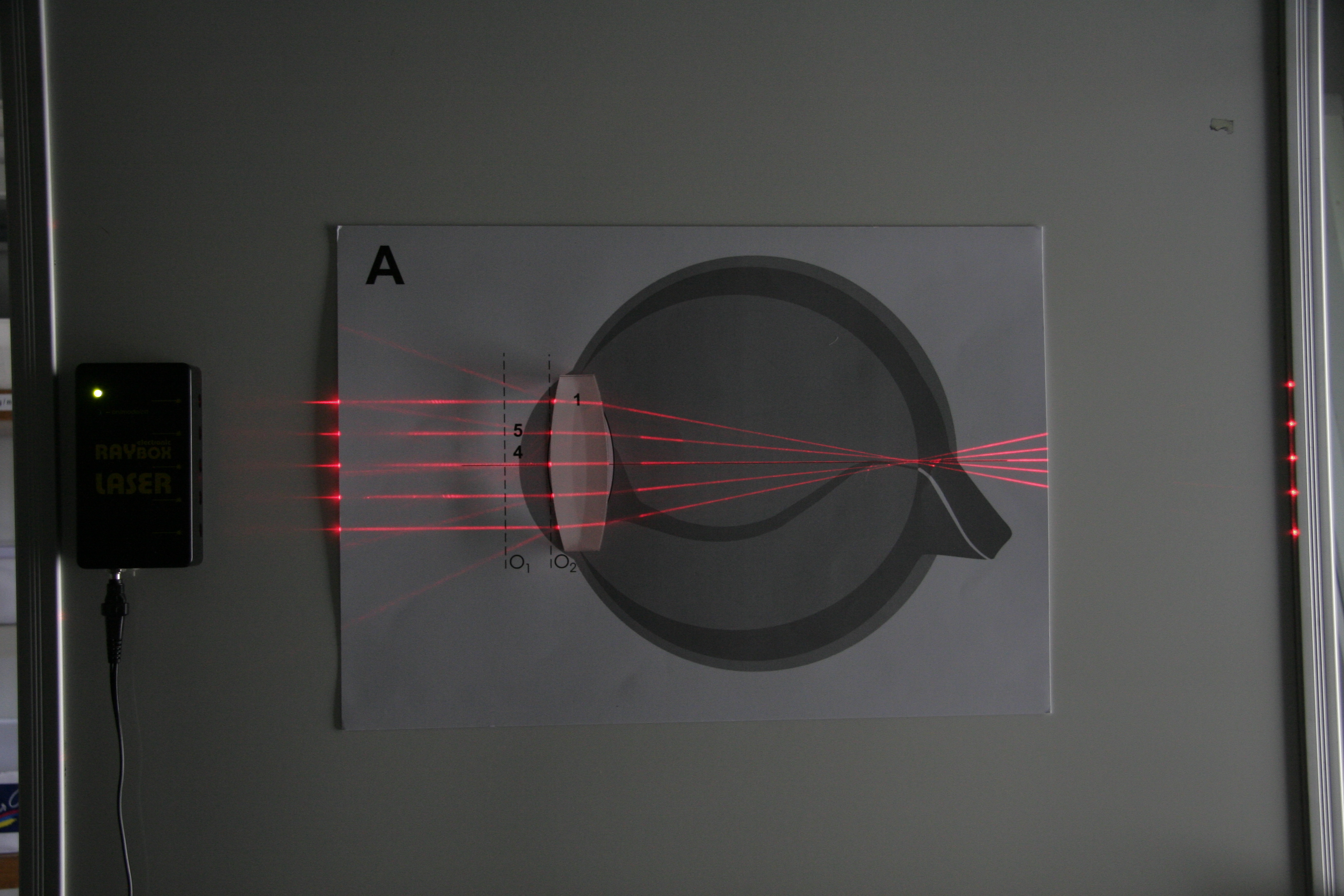
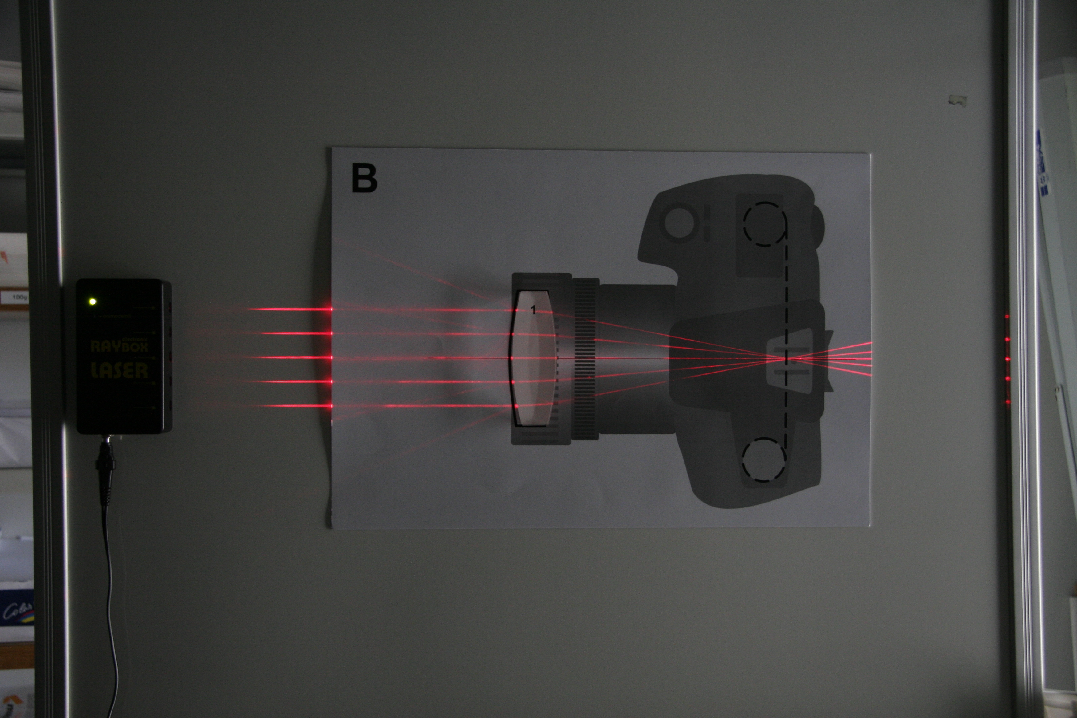
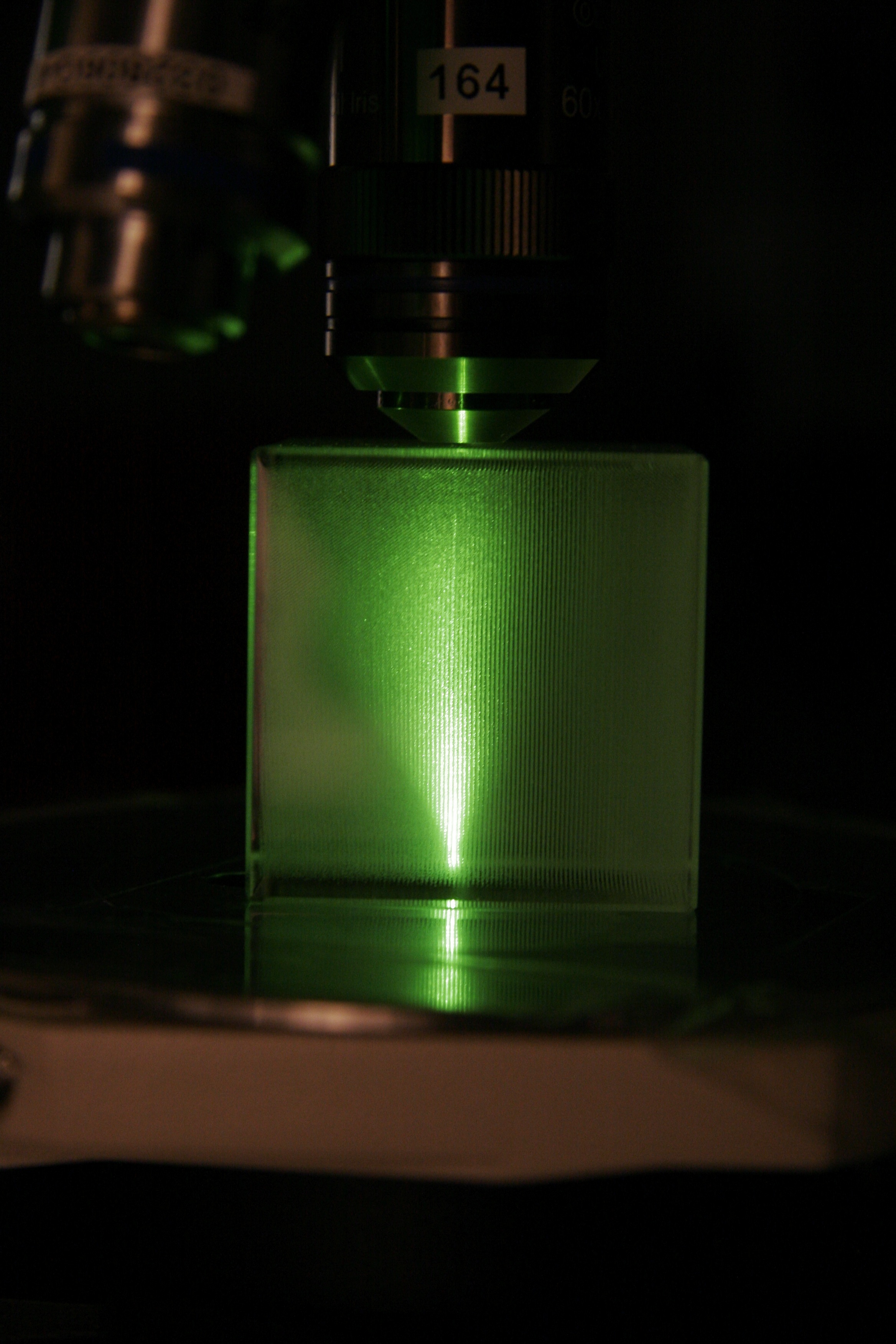
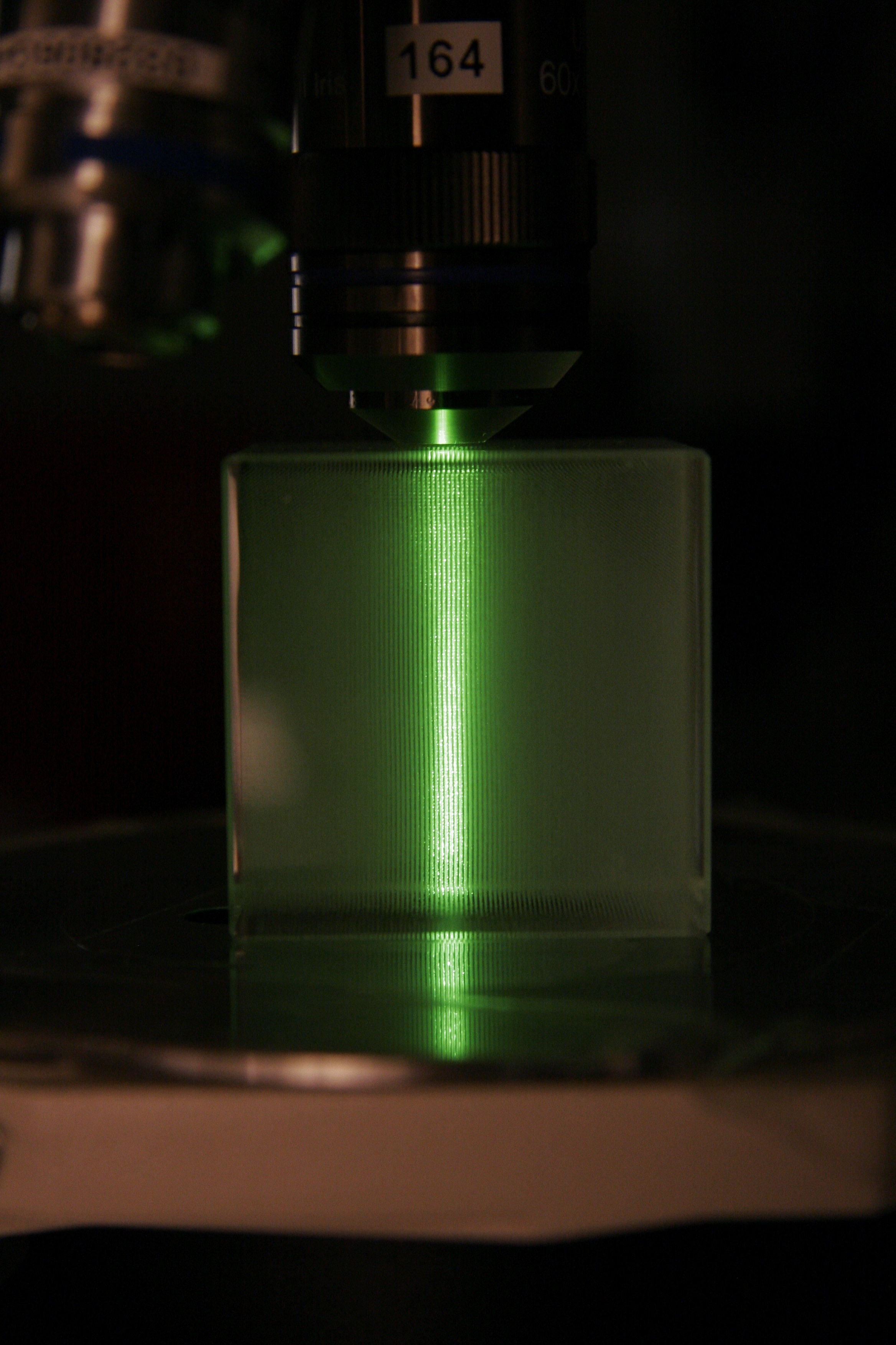
Demonstrate how light gets refracted at the interface of two different media.


Materials

  • clear  waterbath with a 360° protractor on its back wall (self made or eg.  from Pierron)
  • different laser pointers
  • clear water
  • darkish room


Practical Setup

  • Fill  bath with water so that half the protractor is under water.
  • One  student (or teacher) shoots a laser pointer into the water.
  • Laser beam needs to be parallel to protractor surface.
  • Another student may read  incident and exit angle.
  • Discuss.
  • Why is the angle of light changing?
  • What will happen if you change wavelength of laser? 

Warning: do NOT  point laser towards students!


Idea/Implementation

Humberto Ibarra Avila, Britta Schroth-Diez

Refraction II - Coin in Cup

Concept demonstrated

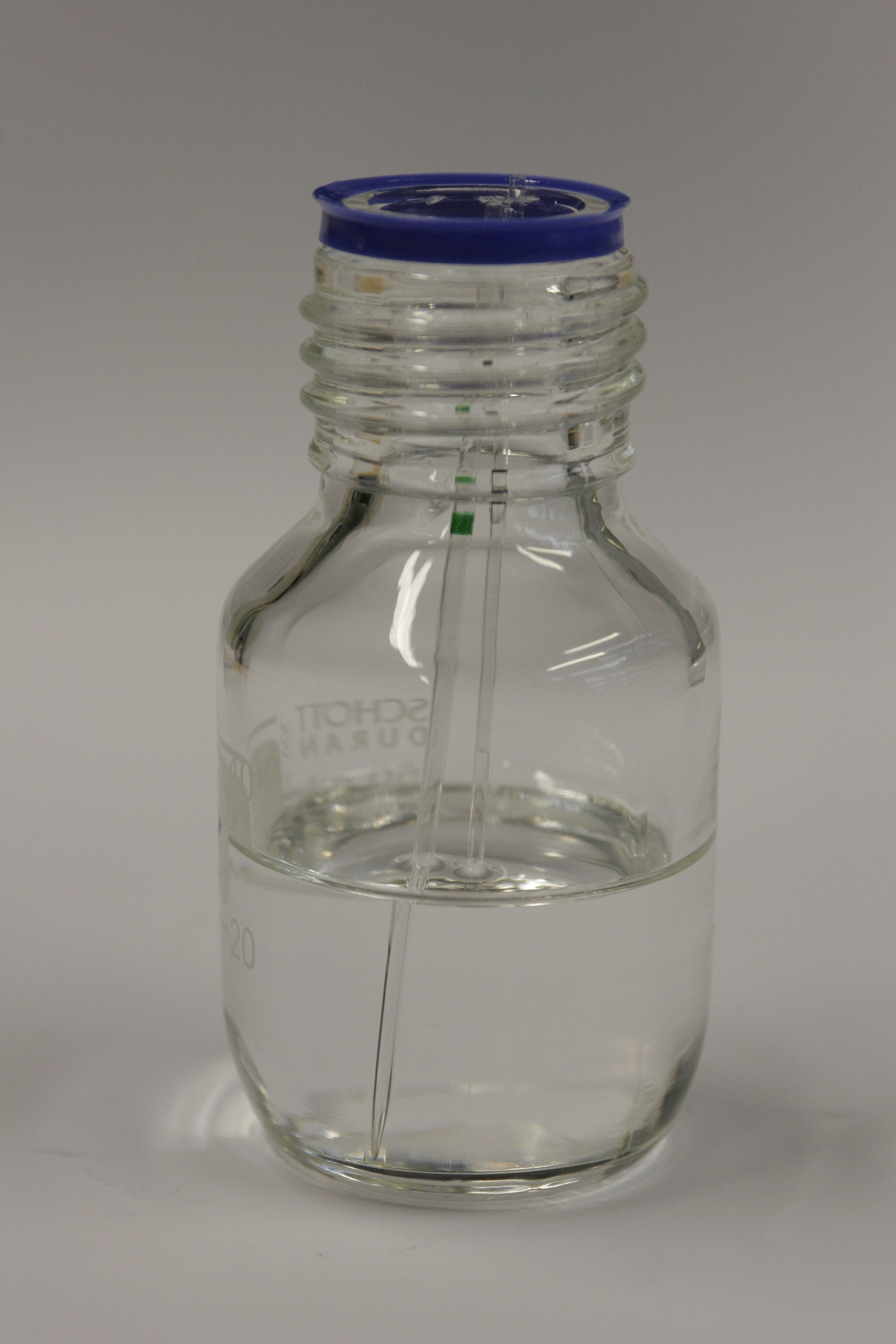
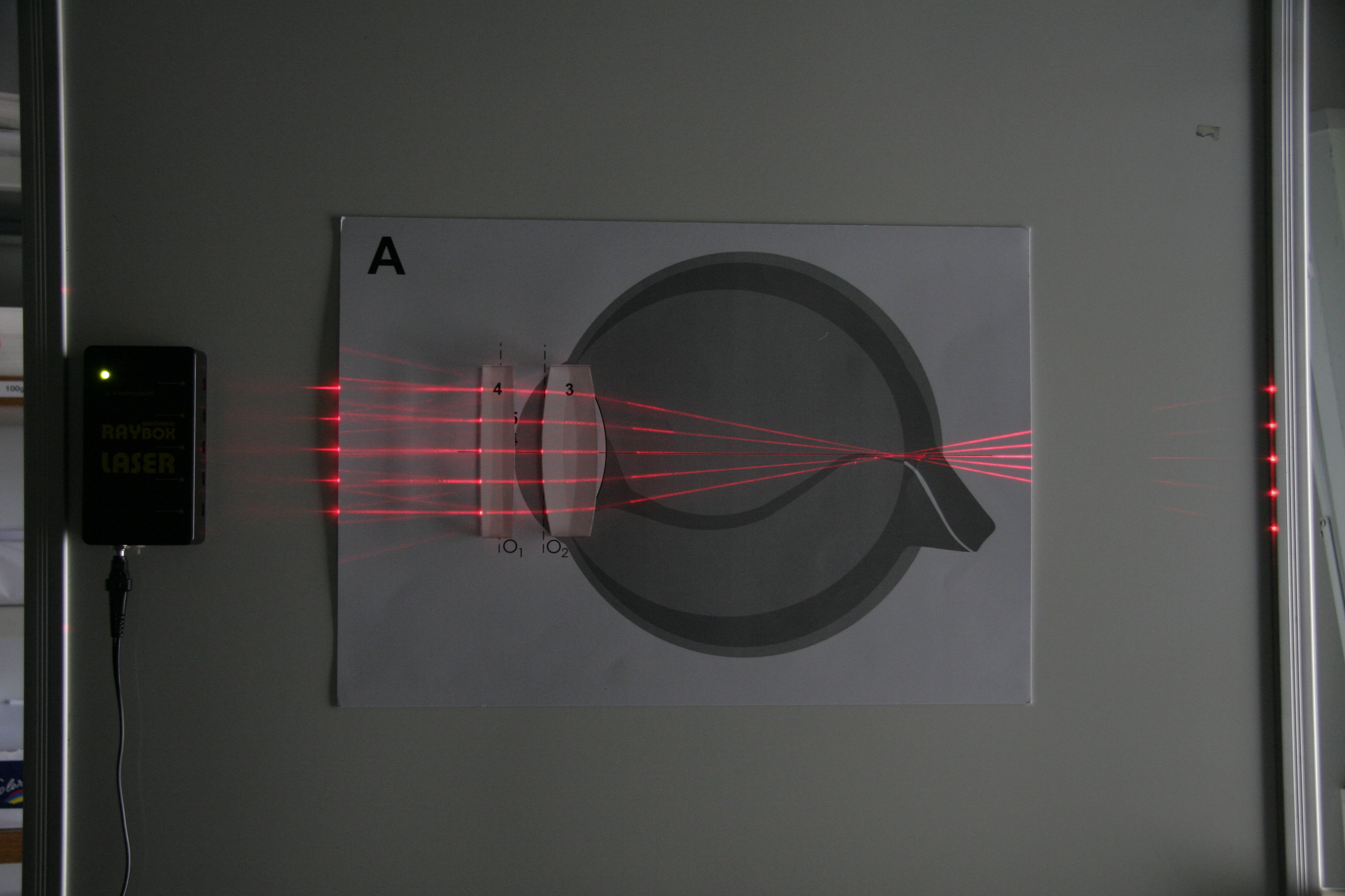
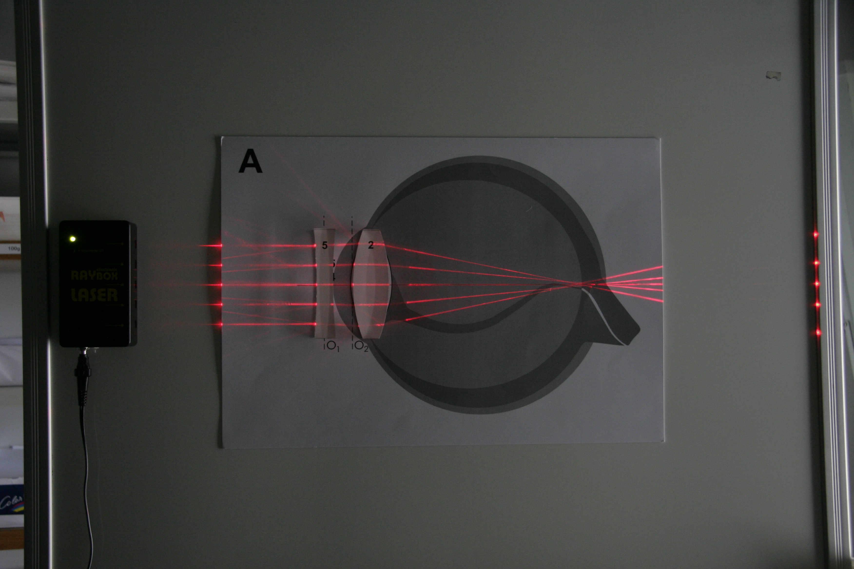
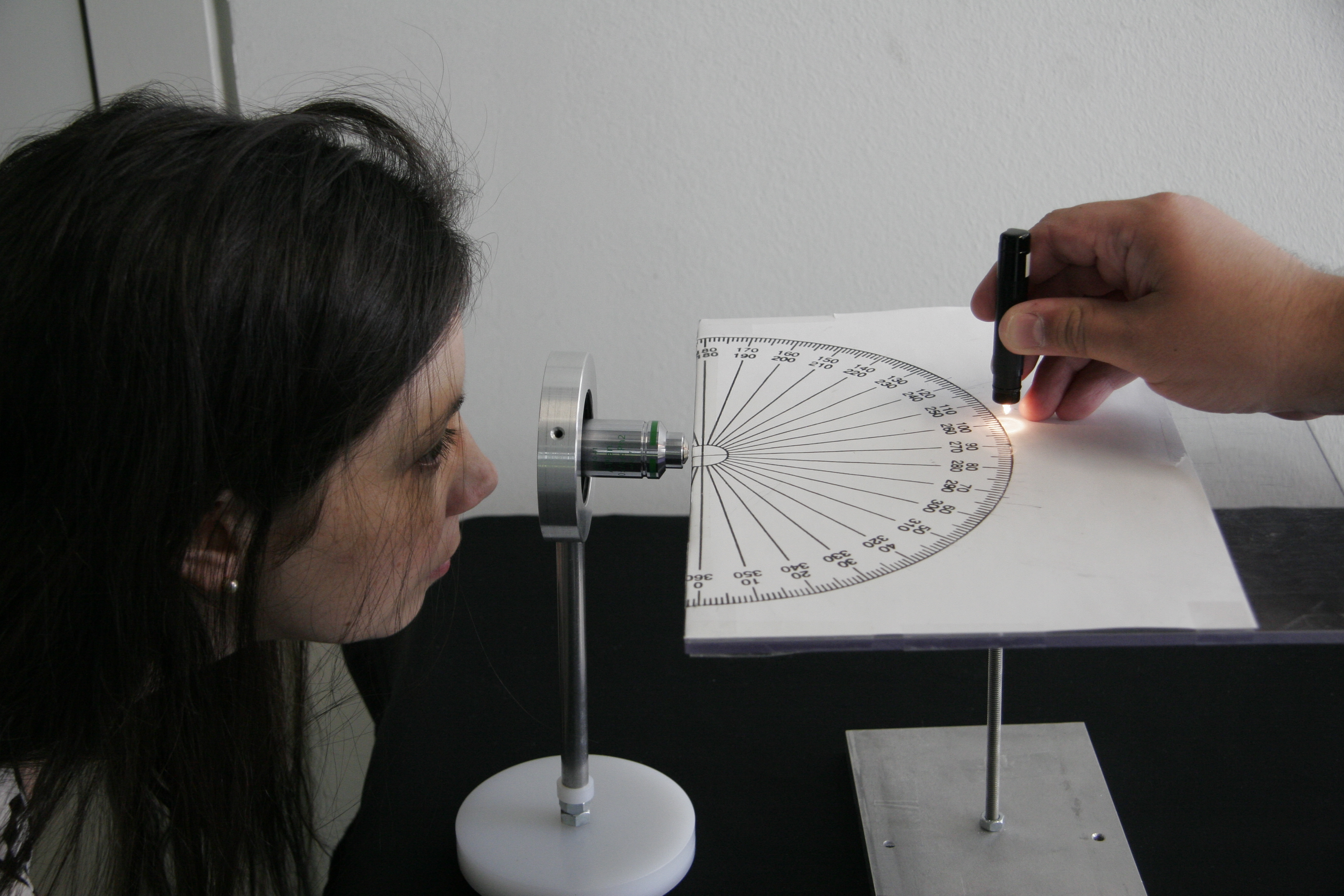
Demonstrates how changes in refractive index change perception.


Materials

  • a cup with a small coin glued to it's bottom
  • a beaker with water


Practical Setup

  • Students  stand in front of the cup such that they just do not see the coin  anymore
  • Teacher slowly fills the cup with water
  • What will the students  see?


Idea/Implementation

Peter Pitrone

Refraction III - Refractive Index Match and Missmatch

Concept demonstrated


Materials


Practical Setup


Idea/Implementation

Ray Optics

Hands-on

Ray Optics

Concept demonstrated


Materials


Practical Setup


Idea/Implementation

Conjugate Planes

Hand-on

Optical Bench I - Conjugate Planes

Concept demonstrated

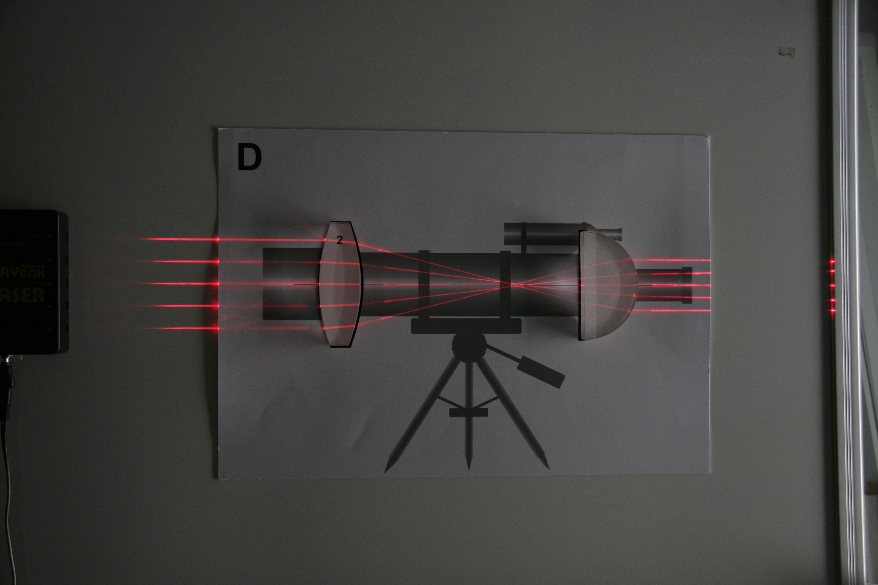
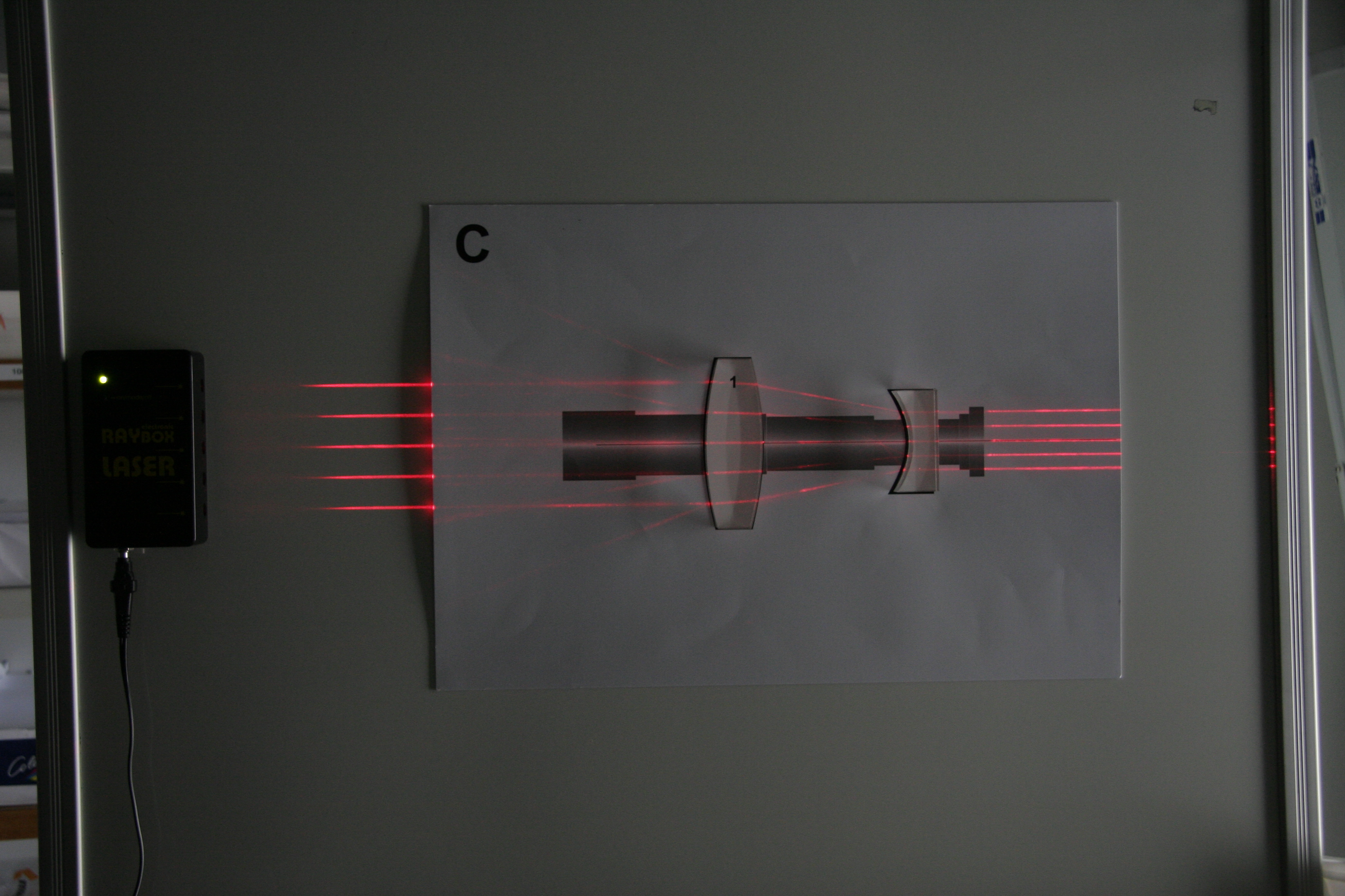
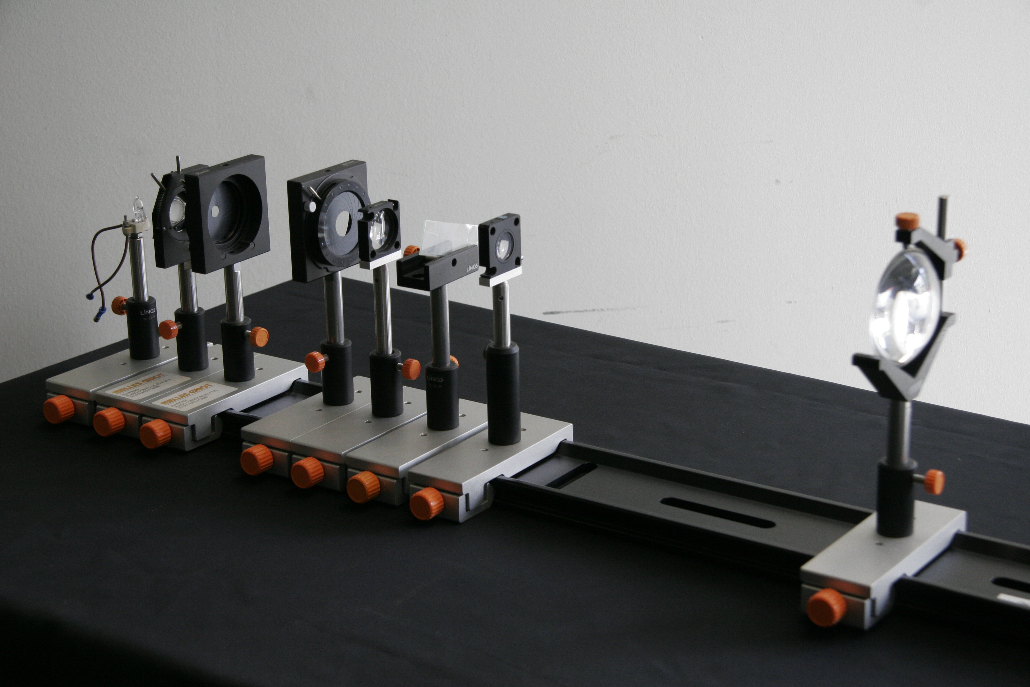
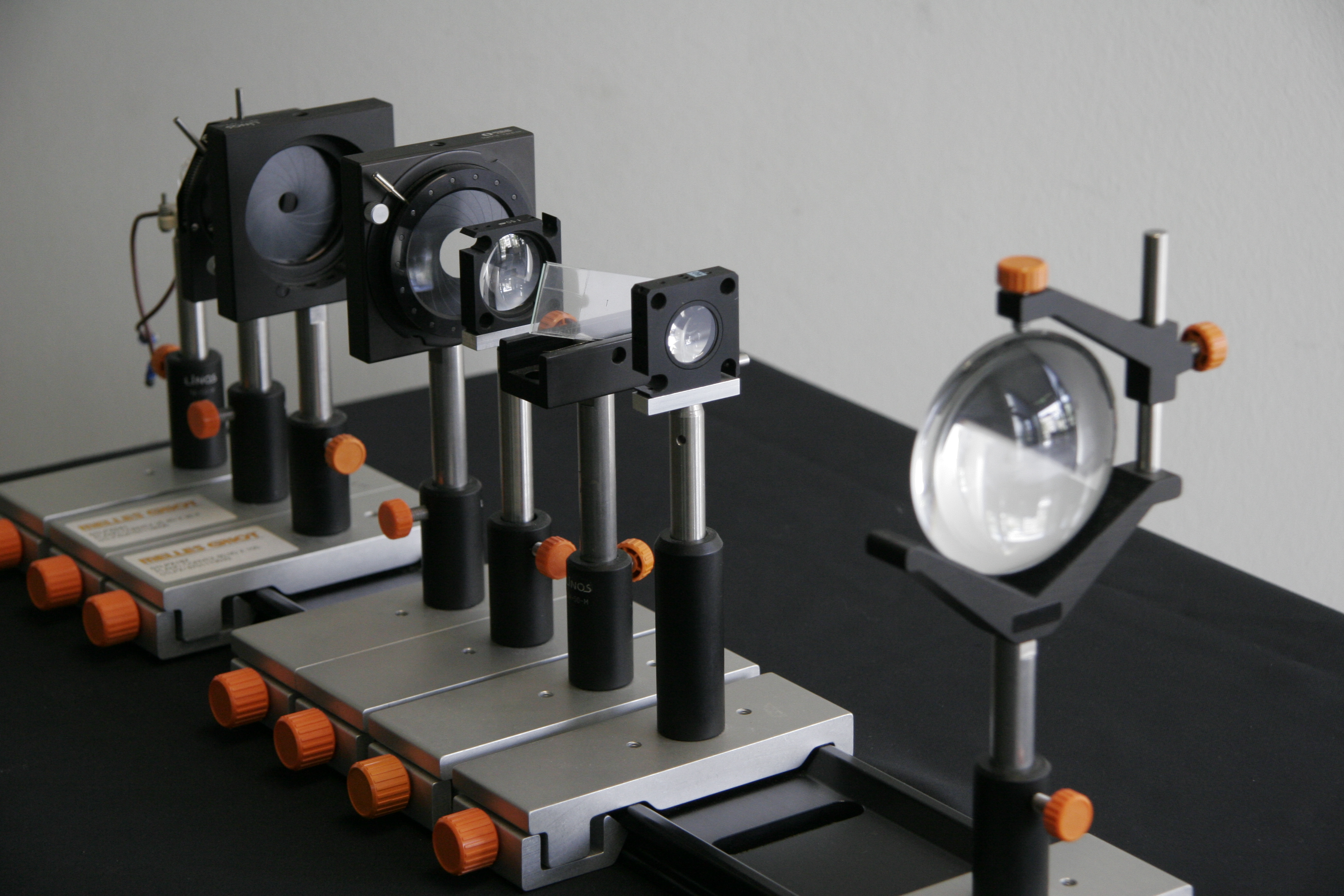
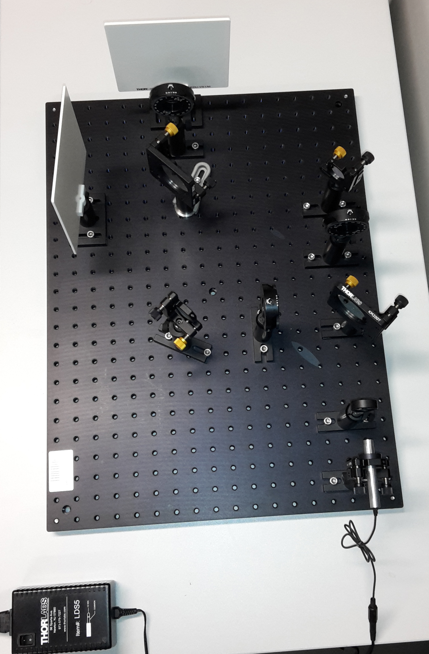
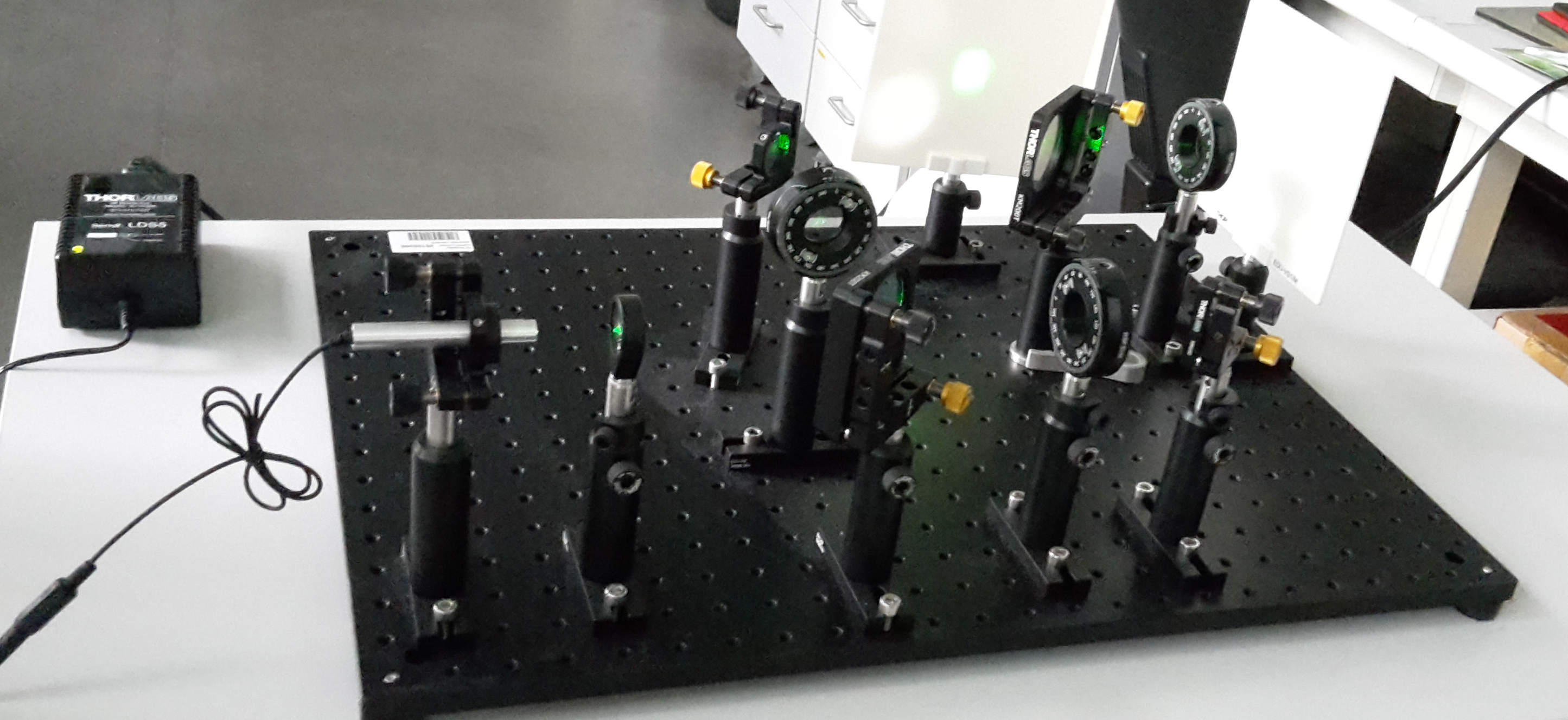
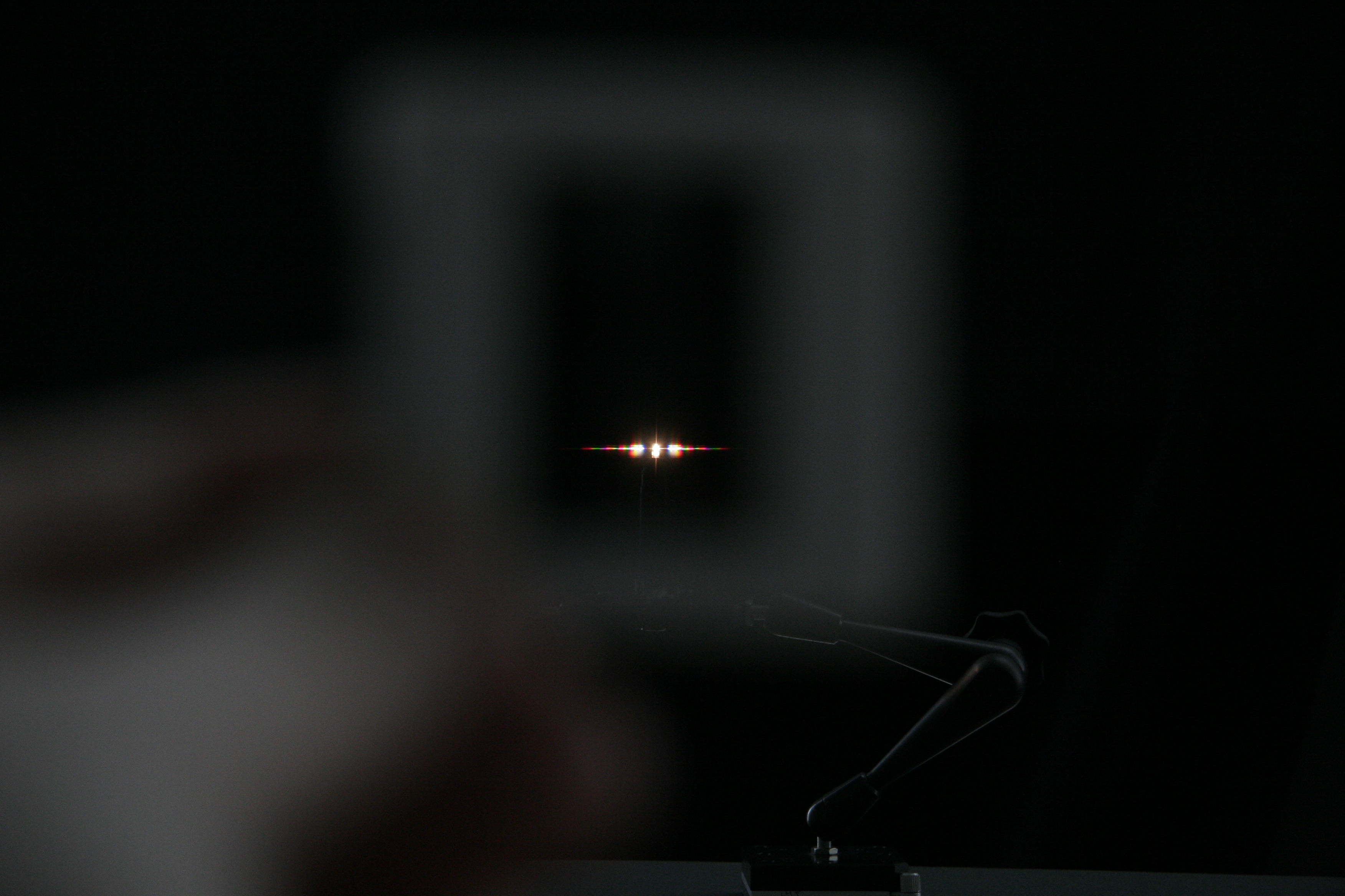
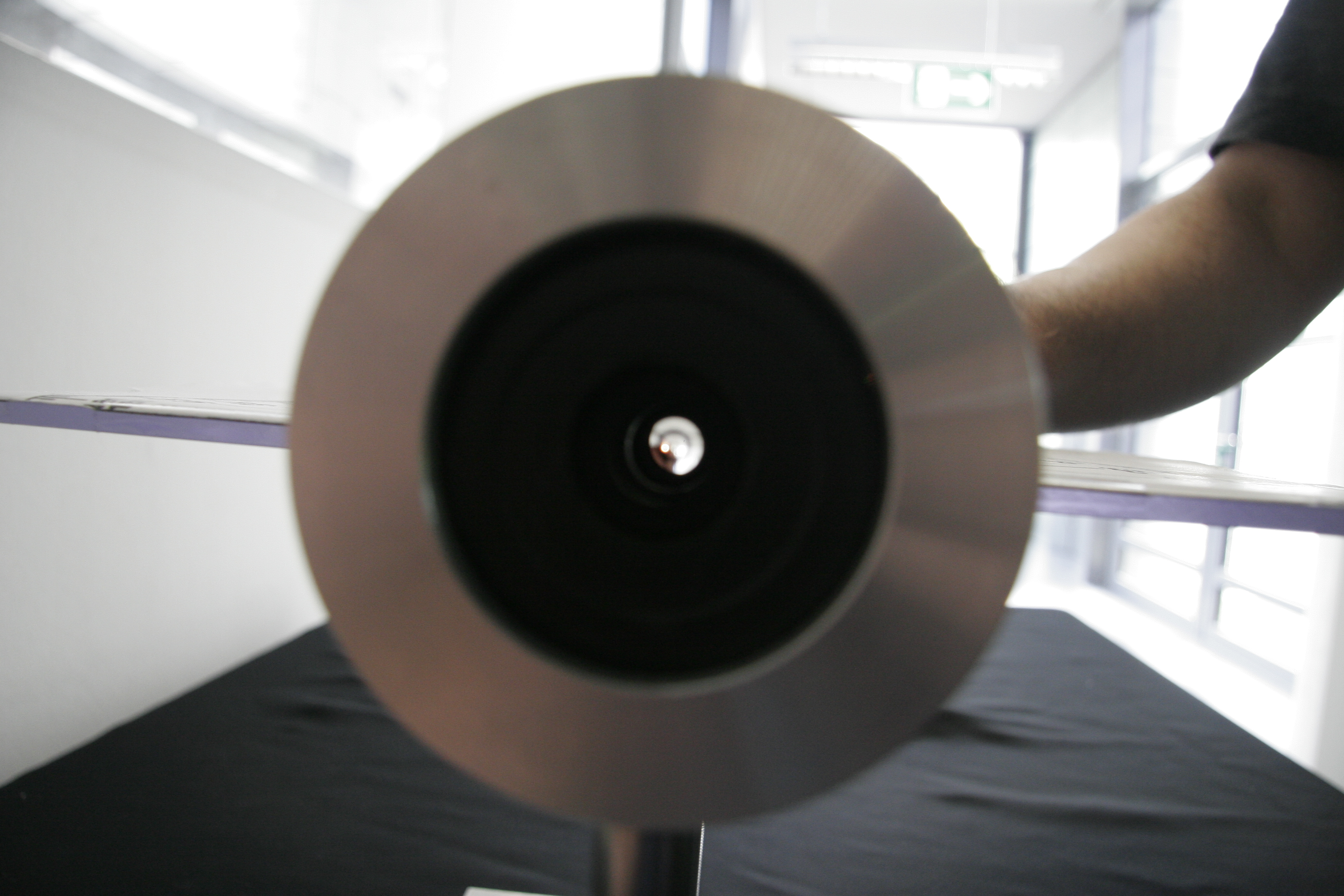
Demonstrates the essential parts of a microscope and explains the concept of conjugate planes: What are the key elements? Where is the back focal plane and what can you see there? Where is the primary image formed?

Materials

A bench with the ability to host several optical elements, in our case: 

  • light source (with filament)
  • collector lens
  • field diaphragm
  • condenser aperture diaphragm
  • condenser front lens
  • sample holder and  sample
  • objective lens
  • eyepiece lens

Parts can be purchased from Qioptiq (fromer Linos), Thorlabs, Newport

Practical Setup

  • students stand around bench while teacher explaines

Then let them find the different optical planes themselves:

  • Use a sheet of paper to find back focal plane and primary image plane
  • Can they see the image of the sample by sitting down and looking through  the eyepiece? (you know it, when they are able to describe the sample (an  arrow? a smiley?) accurately)

Warning: mind to not power up the light  source too much

Idea/Implementation

Kurt Anderson, Jan Peychl

Optical Bench II - Infinity Optics

Concept demonstrated


Materials


Practical Setup


Idea/Implementation

Wave Optics

Hands-on

Ripple Tank

Concept demonstrated


Materials


Practical Setup


Idea/Implementation

Interferometer

Concept demonstrated


Materials


Practical Setup


Idea/Implementation

Diffraction

Hands-on

Diffraction Demo

Concept demonstrated

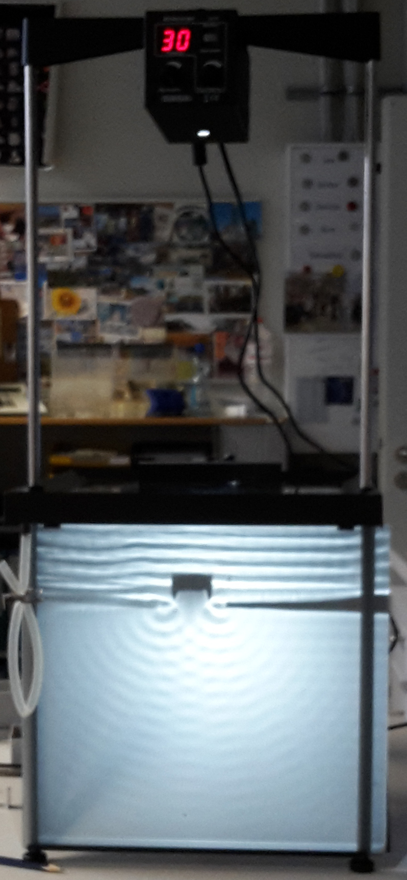
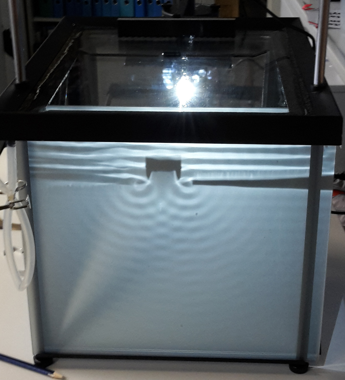
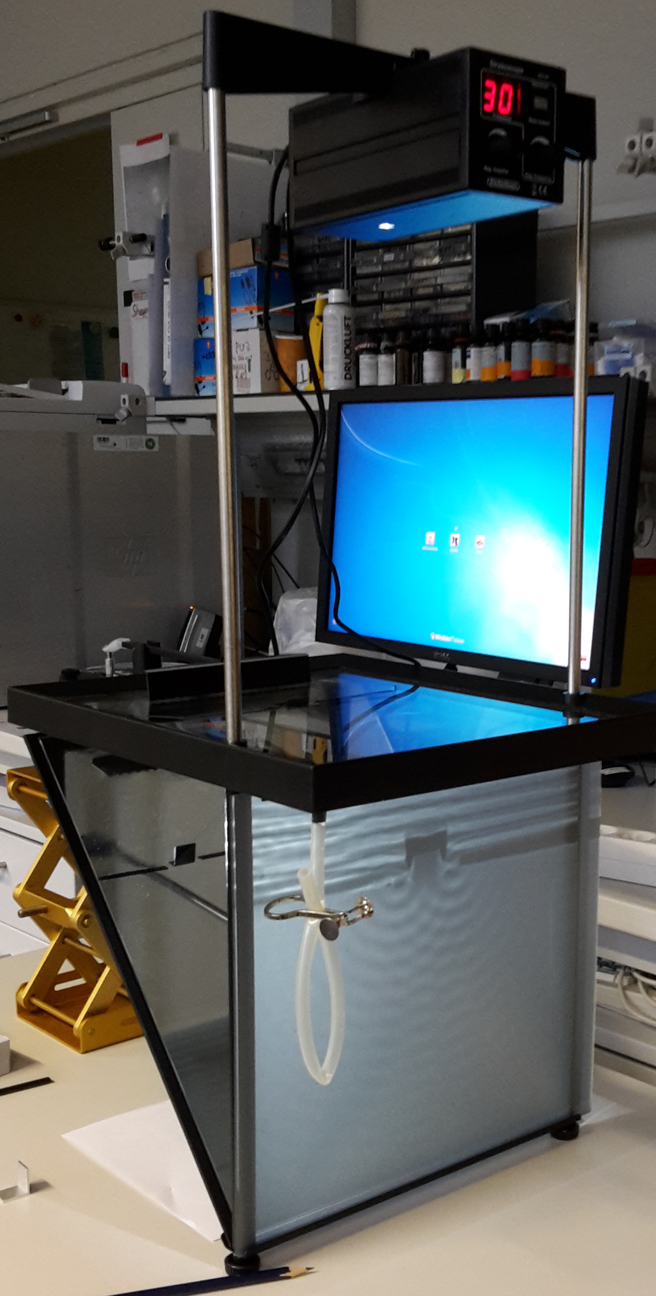
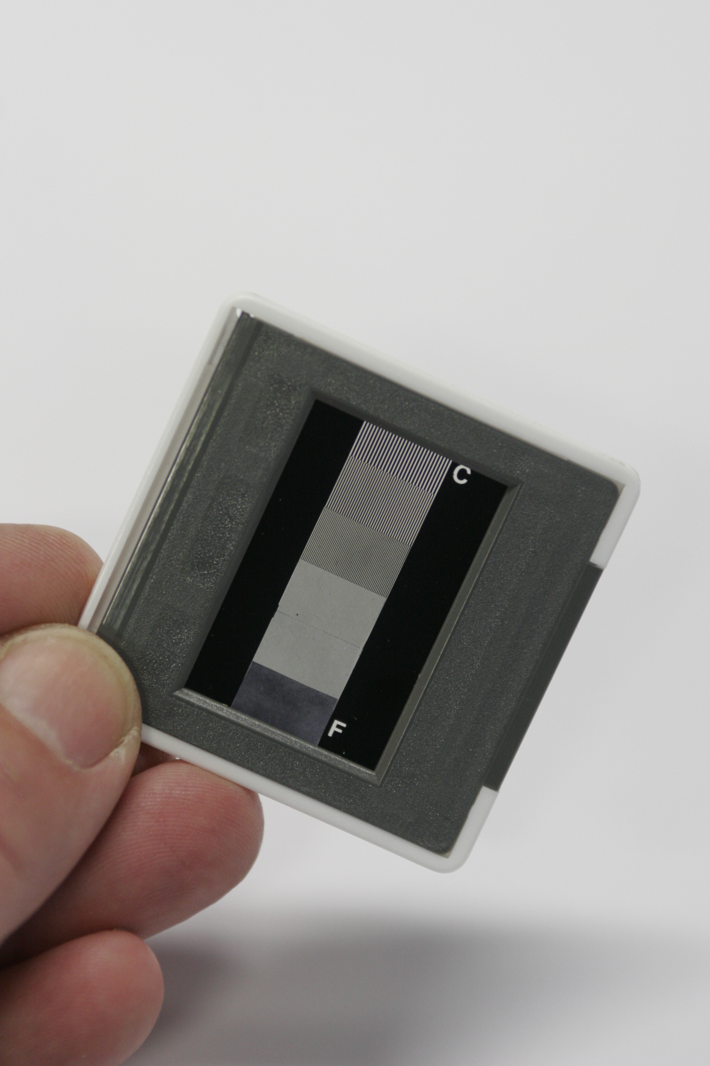
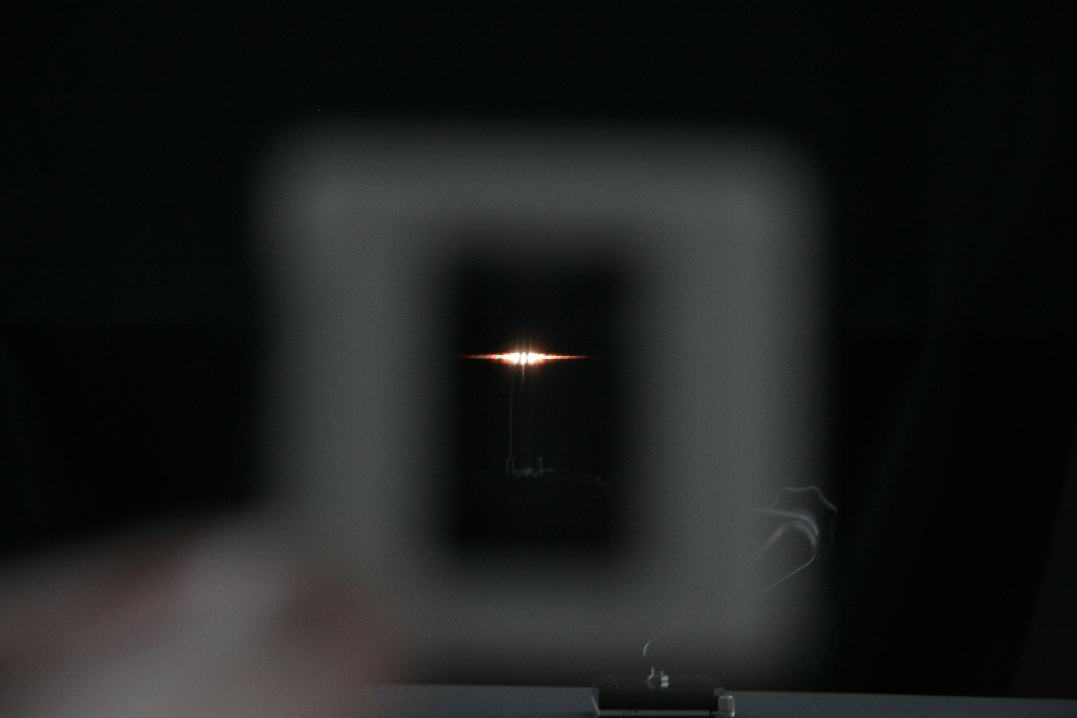
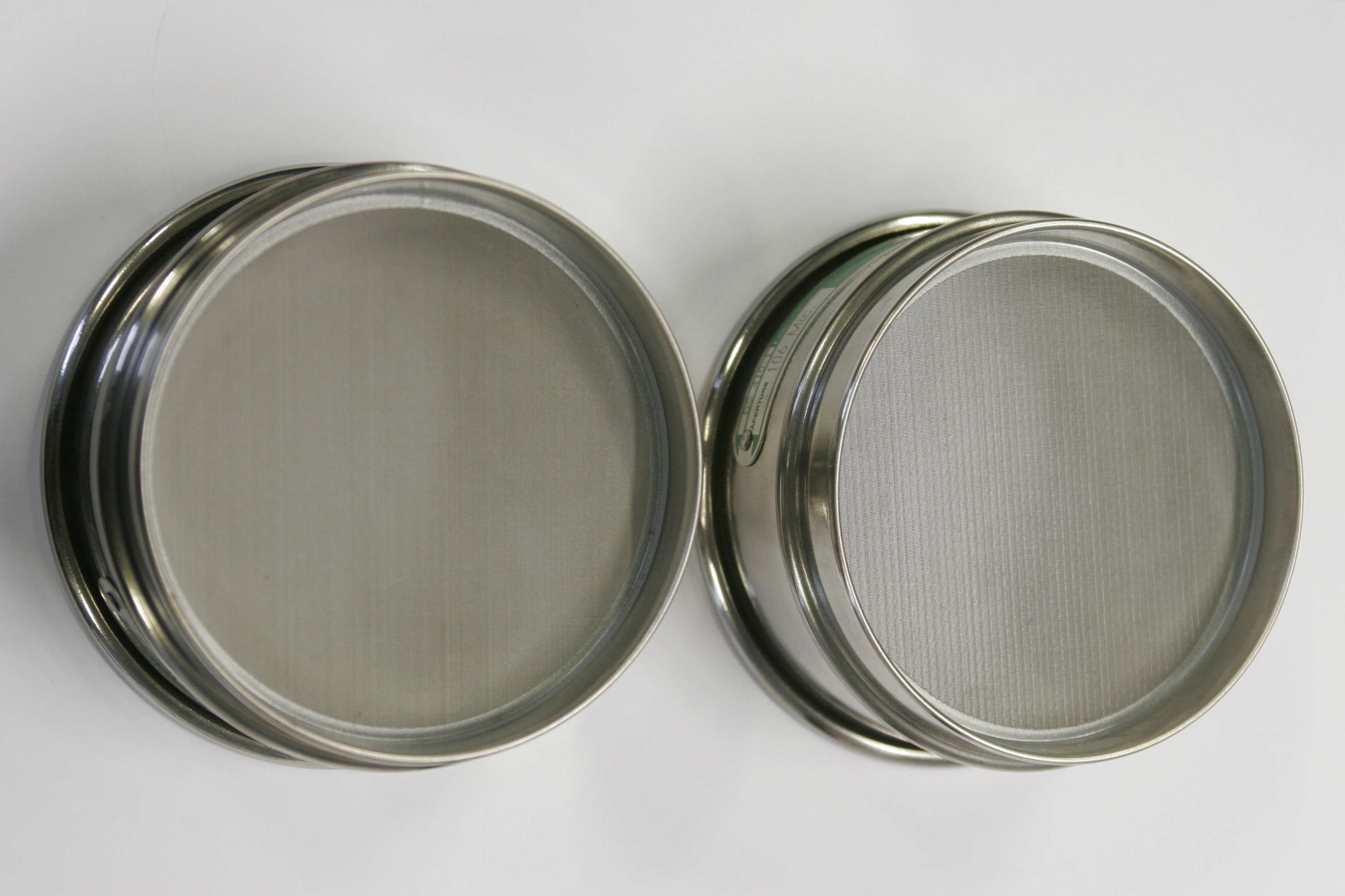
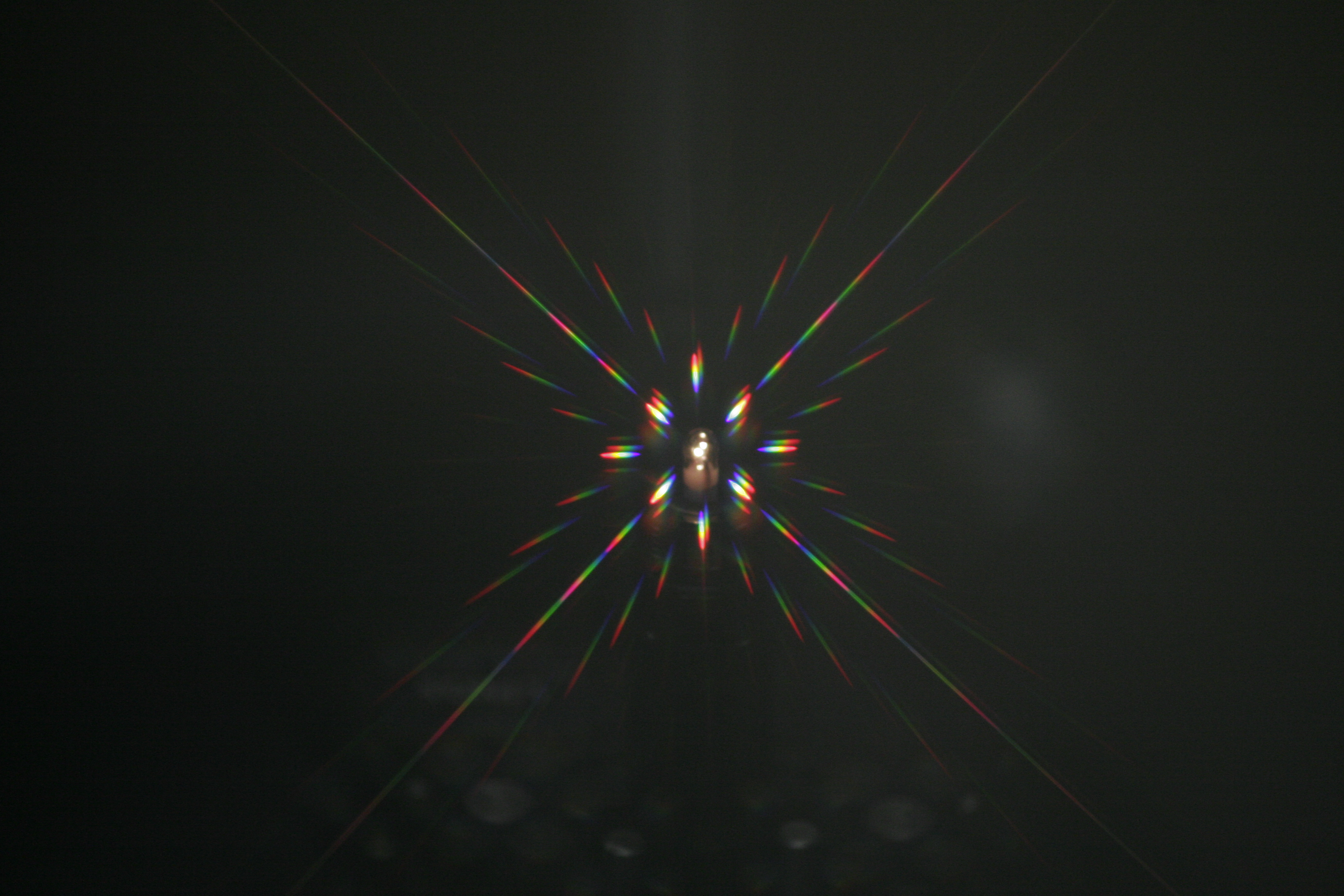
Demonstrated how different wavelengths of light are scattered by differently sized objects.


Materials

  • You can use anything that has a mesh with a small enough grating to show the effect of differently sized object features. In our case we use 

         - sieves ("Sortiersiebe") with two different gratings (eg. 106 and 130μm)
         - dia-slides each with both a coarse and a fine grating (have them printed directly for this purpose)

  • a pointy light source
  • a dark room


Practical Setup

  • each  student gets his/her own diffraction gratings
  • teacher holds light
  • students observe and discuss with teacher different aspects of  diffraction: How do the different wavelength behave? What is the effect  of a smaller/bigger gratings? What does this mean translated into a  microscope?


Idea/Implementation

Peter Evennett, Humberto Ibarra Avila, Britta Schroth-Diez

Numerical Aperture

Hands-on

What is Numerical Aperture? Milky Glass Block Demo

Concept demonstrated

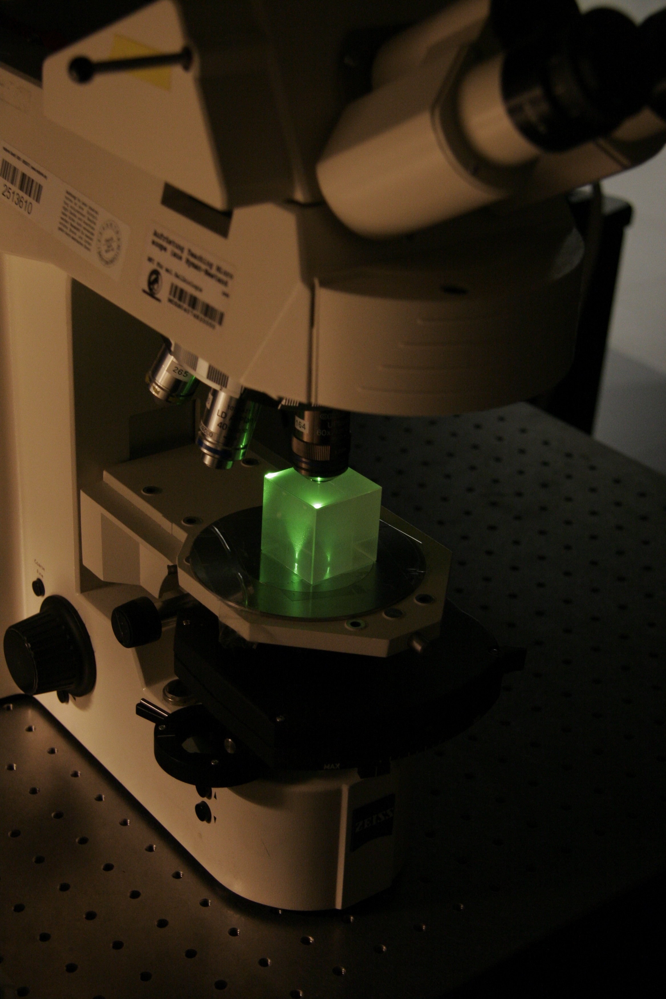
 Demonstrates the effect of both objective and condenser Numerical Aperture.


Materials

  • upright stand (for better visibility of objectives)
  • microscope stand w/o stage (for more space)
  • milky glass block
  • ideally condenser with manual aperture diaphragm
  • two transmitted light light sources (eg. Halogen lamps or white LEDs) ... one for the TL port, one for the RL port
  • two differently coloured filters (to better distinguish top and bottom light), one in either (transmitted and reflected) beam path


Practical Setup

  • Teacher demonstrates and explains while students stand around setup watching.
  • Students might than also try to change aperture size and objectives.


Idea/Implementation

Peter Evennett, Jan Peychl

Milky glas block demo - condenser NA

NA of the condenser visualized by illumination of the milky glas block through the condenser.

High condenser NA

High condenser NA (open aperture diaphragm) visualized by illumination of the milky glas block through the condenser.

Low condenser NA

Low condenser NA (closed aperture diaphragm) visualized by illumination of the milky glas block through the condenser.

Numerical Aperture Measurements

Concept demonstrated

Demonstrates the effect of the Numerical Aperture of an objective. Opportunity to practice some calculations around resolutiona and NA.


Materials

  • pointy light source
  • a stand with a horizontal 180° Protractor
  • a stand with a mount for an objective at the same height as the protractor stand
  • two air objectives with as different NAs as possible
  • a calculator


Practical Setup

  • Start by mounting the objective with the lower NA.
  • Let one student hold the light source onto the protractor at 0° (in a straight line with the objective)
  • another student sits behind the objective and tries to see the light through the objective. Make sure the student finds the best possible focus point.
  • Then let the first student move the lamp slowly (!) around one side of the protractor.
  • The second student says "stop" as soon as the light moves out of his (the objective's) field of view.
  • Mark the angle on the protractor. 
  • Switch to the higher NA objective and repeat steps above.
  • The clear difference in the size of the field of view of the different NA objectives is usually quite impressive by itself. 
  • Also, from the angles, let the students calculate backwards to the NA ... does it match the number written on the objective?
  • Taking the NA, let the students calculate the resolution of both objectives for a given wavelength ... discuss the difference.
  • With the objectives at hand (ie. air objectives) what is the highest resolution obtainable (taking a again a wavelentgh in the middle visible range)? What would one have to do in order to reach better resolutions?


Idea/Implementation

Humberto Ibarra Avila, Silke White

NA measurements

NA measurements 2